Illustration
The purpose of illustration is to record the things we find, whether they are excavated layers, artefacts or structures, so that written descriptions make more sense and the information is preserved for the future. Artefacts can be photographed and studied at length in a museum, so these are not usually illustrated on site. However, the layers, features and structures uncovered during an excavation may only be visible for a short time when the excavation is happening, and it is vital to make an accurate and permanent illustrative record of them. Every context must be included in a plan or section and photographed – however insignificant. It may turn out to be much more important than it first seems, once post-excavation analysis has been carried out.
Plans
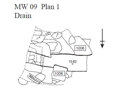
Plans are measured drawings of layers and structures on excavations, recorded horizontally. This means that the finished plan should represent the surfaces being drawn as if from above, to scale (usually 1:20 or 1:10, but for large areas 1:100 is sometimes used). Plans are drawn on site, and then inked-in (and increasingly, computer-digitised) afterwards to create a permanent record.

A plan must always be carefully located within an excavation area, with grid points marked at the corners. The site grid is represented by graph paper on a drawing board: secured over this is a blank sheet of semi-transparent drawing film which is drawn on in pencil. If the plan is to be drawn at 1:20, then each centimetre square on the graph paper represents 20 cm on the site. A 1 metre square wooden frame strung out in 20 by 20 cm squares inside (called a planning frame) is placed over the archaeology to enable the planner to visualise the grid on the ground, and draw more accurately. The frame must be absolutely level (not always easy on a sloping site) otherwise the drawing will be distorted by perspective. Sometimes it is necessary to position a frame above the ground using adjustable props, making sure it is level with a spirit-level. If there is a gap below the frame, a plumb-bob on a string is used to transfer the grid intersections vertically to the surface being drawn. A level or total station is used to measure height by taking level points on the planned area. These are marked on the plan.
Planning is a skill which requires much practice and patience, and even then some people find it difficult to get it right. Many excavation teams have a full-time ‘planner’ – somebody with good visual and drawing skills who can work quickly, consistently and accurately and make sure that this vital recording activity is done properly.
Sections
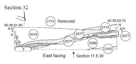
Section-drawings are measured drawings of sections – vertical cuts though layers and structures on excavations. This means that the finished plan should represent the surfaces being drawn as if face-on from the side, to scale (usually 1:10, but for larger sections 1:20 or 1:100 is sometimes used). Sections are drawn on site, and then inked-in (and increasingly, computer-digitised) afterwards to create a permanent record.
A section drawing must always be carefully located within an excavation area, with grid points marked at the corners. The drawing scale is represented by graph paper on a drawing board: secured over this is a blank sheet of semi-transparent drawing film which is drawn on in pencil. If the plan is to be drawn at 1:10, then each centimetre square on the graph paper represents 10 cm on the site. Metal pins or pegs are placed at the top of each end of the section and a string tied between them. The string is levelled at each end using a level or total station, and the position of each end is recorded on the site grid.
The shape and detail of the section will be measured vertically downwards from the string using a hand-tape. To locate a position along the string, another tape is strung out between the pins at either end. Sections are drawn of the sides of excavation trenches or of blocks of unexcavated material called ‘baulks’, showing all the layers which have already been dug through - or of individual features such as post-holes or ditches, which are always quarter or half-excavated first, and the section is drawn before the rest of the fill may be removed.
Sections can be drawn at the end of an excavation when all the digging is complete, or they may be drawn in stages as work continues: these are called cumulative sections. These are particularly useful for recording temporary baulks (blocks of unexcavated earth which are left in place to provide a vertical section across a particular excavation area for a temporary period, or sometimes to leave a strip of ground surface for access purposes, but which are excavated before the end of the dig).
 A plan must always be carefully located within an excavation area, with grid points marked at the corners. The site grid is represented by graph paper on a drawing board: secured over this is a blank sheet of semi-transparent drawing film which is drawn on in pencil. If the plan is to be drawn at 1:20, then each centimetre square on the graph paper represents 20 cm on the site. A 1 metre square wooden frame strung out in 20 by 20 cm squares inside (called a planning frame) is placed over the archaeology to enable the planner to visualise the grid on the ground, and draw more accurately. The frame must be absolutely level (not always easy on a sloping site) otherwise the drawing will be distorted by perspective. Sometimes it is necessary to position a frame above the ground using adjustable props, making sure it is level with a spirit-level. If there is a gap below the frame, a plumb-bob on a string is used to transfer the grid intersections vertically to the surface being drawn. A level or total station is used to measure height by taking level points on the planned area. These are marked on the plan.


